Tabla de contenido:
- Autor John Day day@howwhatproduce.com.
- Public 2024-01-30 08:43.
- Última modificación 2025-01-23 14:40.
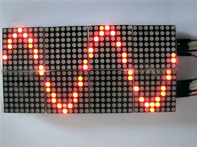
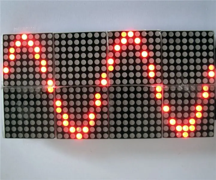
Es un proyecto por diversión solo para ver qué tan lejos en velocidades podría empujar una pantalla de matriz de puntos MAX7219. Y en lugar de hacer que ejecutara el "juego de la vida", decidí hacer un "alcance" con él. Como comprenderá por el título, este no es un reemplazo de un osciloscopio real:-).
Como no planeo usar esto de manera seria, no haré una placa de circuito impreso para ello. Tal vez, solo tal vez lo ponga en una placa de perforación, pero por ahora está, y permanecerá, en una placa de pruebas. Además, no hay amplificador / atenuador de entrada, debe suministrar una señal entre 0 y 3.3V, no sea negativo o superior a 3.3V ya que puede dañar el microcontrolador.
Paso 1: hardware
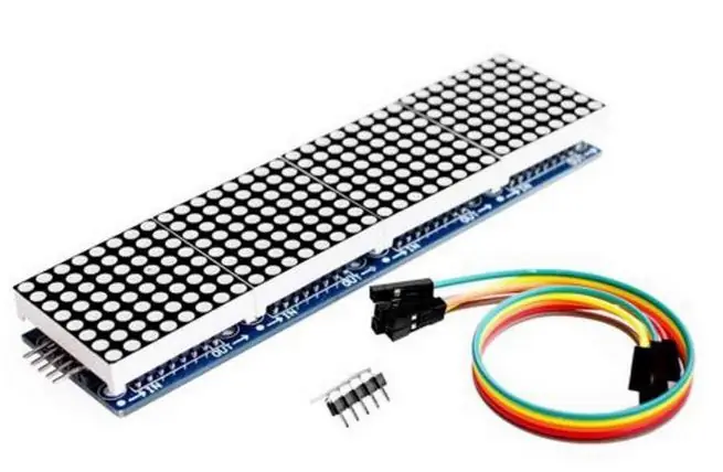
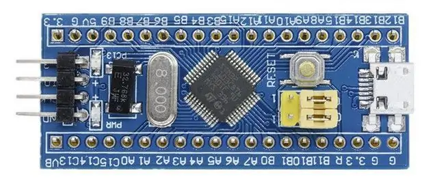
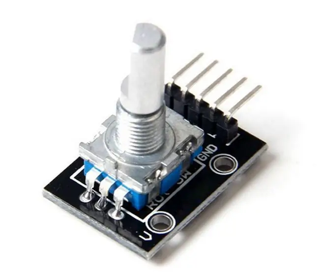
Es barato, muy barato si compra las piezas en China a través de eBay o sitios similares. Utiliza una placa de desarrollo STM32F103C8, a veces llamada "pastilla azul" que compré por alrededor de 2 euros (o USD, tienen casi el mismo valor, finales de 2018), dos pantallas de matriz de puntos de 8x8x4 con chips MAX7219, compradas por 5 euro la pieza y un codificador rotatorio de aproximadamente 1 euro.
Por supuesto, se necesita una fuente de alimentación que proporcione 3,3 V a unos pocos cientos de miliamperios. El regulador de voltaje de la placa de desarrollo STM32F103C8 no se utiliza, no puede proporcionar suficiente corriente para las pantallas. La hoja de datos para el MAX7219 especifica que el voltaje de suministro operativo debe estar entre 4.0 y 5.5V pero funciona bien con 3.3V, quizás no cuando lo usa en un ambiente muy caliente o frío, pero a 20 Celsius está bien. Y ahora no tengo que usar convertidores de nivel entre el microcontrolador y los tableros de visualización.
Paso 2: construir
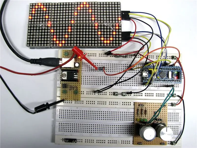
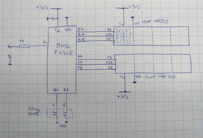
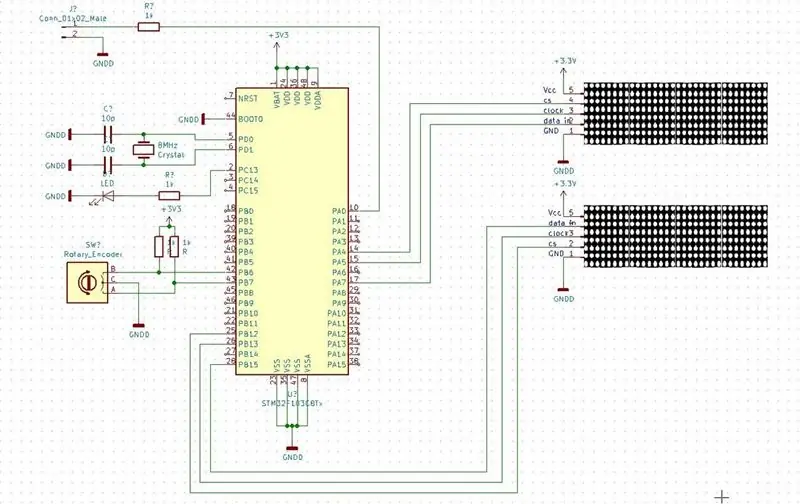
Cuando miras la imagen, es posible que veas que utilizo las líneas eléctricas en las placas de prueba de una manera no convencional, ambas líneas en la parte superior son el riel positivo y las dos en la parte inferior son el riel de tierra. Es la forma en que estoy acostumbrado a hacerlo y funciona bien, hace que la configuración se parezca un poco más a los esquemas que dibujo. Además, he hecho muchas tablas pequeñas con partes que puedo conectar a la placa para acelerar las cosas y todas están configuradas para usar las dos líneas superiores como positivas y las líneas inferiores como tierra. Como dije, la resolución es de 4 bits (16 niveles), y como hay leds de 4x8 uno al lado del otro, solo hay 32 puntos de muestra (pts). Compare eso con un Rigol Rigol DS1054Z (8 bit y 12Mpts) y verá que esto no es un juguete. Cuál es el ancho de banda real, no lo sé, lo he probado hasta 10 kHz y funciona bien.
Paso 3: programas
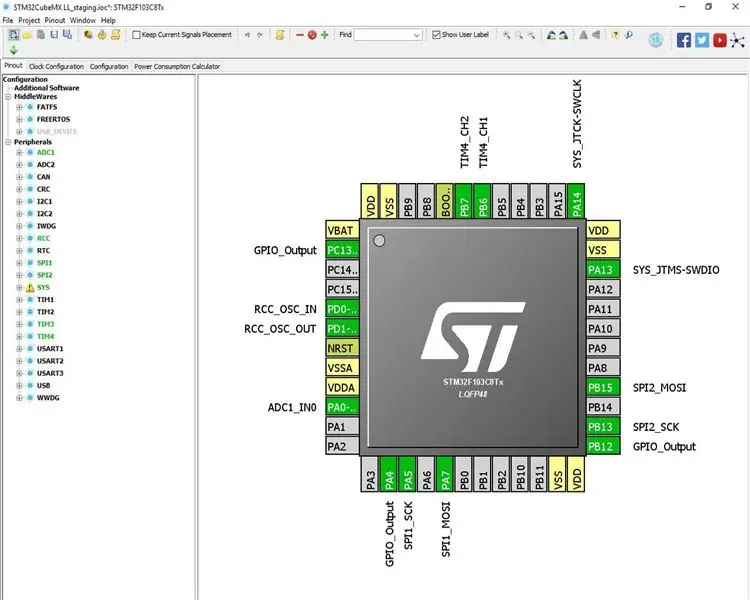
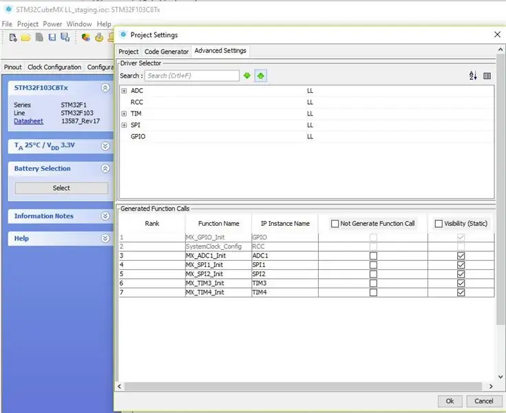
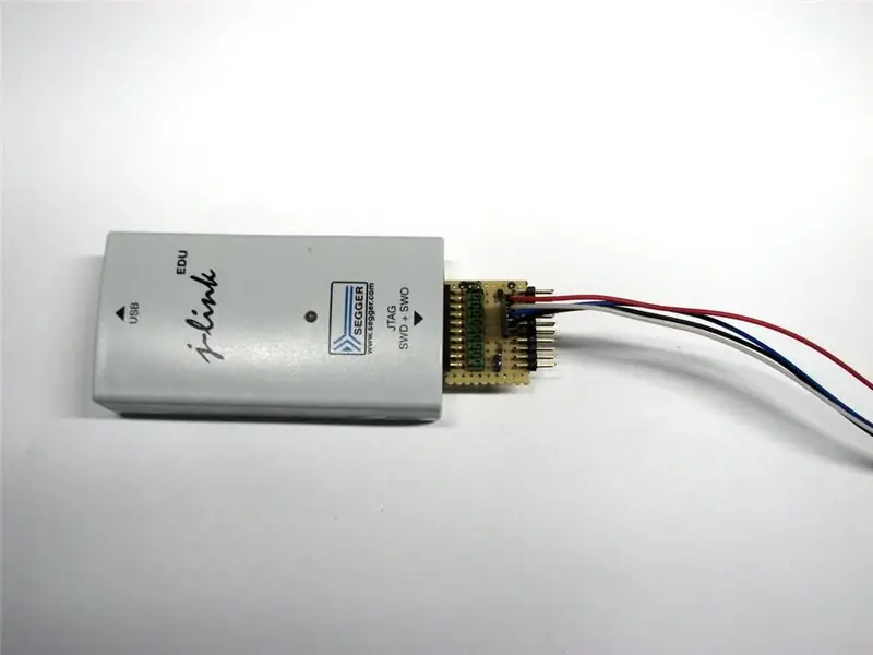
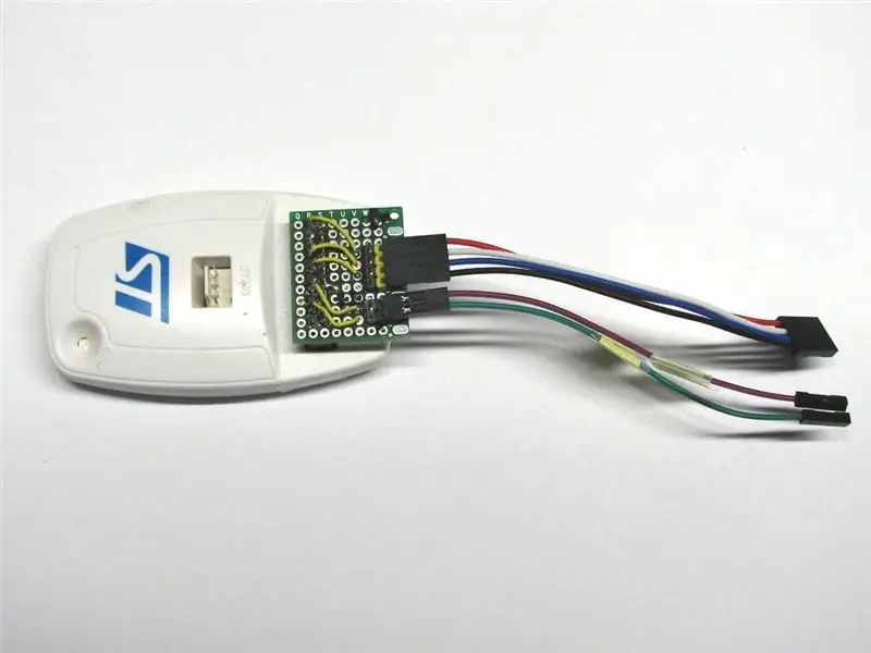
El IDE que utilizo es Atollic TrueStudio, que a principios de este año (2018) fue adoptado por ST Micro Electronics y está disponible de forma gratuita, sin límite de tiempo, sin límite de tamaño de código, sin pantallas molestas. Junto a él, utilizo STM32CubeMX, un programa que me proporciona el código de inicio y genera la inicialización de todos los periféricos. Y tiene una visualización de todos los pines del microcontrolador y su uso. Incluso si no usa STM32CubeMX para generar código, esto es muy útil. Una cosa que no me gusta es el llamado HAL, que es el predeterminado de STM32CubeMX. Prefiero el método de trabajo LowLayer.
Para programar el microcontrolador utilizo el programador / depurador ST-Link de ST Micro Electronics o el J-Link fabricado por Segger. Ambos dispositivos no son gratuitos, aunque puedes comprar copias chinas de ellos por unos euros.
Paso 4: Acerca del código
Los MAX7219 se dirigen a los LED en lo que yo llamo una forma horizontal, 8 LED uno al lado del otro. Para un osciloscopio, habría sido más fácil tener 8 LED uno encima del otro, por lo que hice un búfer de cuadro simple en el que se escribe con datos en forma vertical y se lee en la forma horizontal requerida. El MAX7219 usa un código de 16 bits por cada 8 LED, donde el primer byte se usa para direccionar la línea seleccionada. Y como hay cuatro de estos módulos apilados uno al lado del otro, con sus entradas conectadas a las salidas del módulo anterior, tienes que enviar esos 16 bits cuatro veces para llegar al último módulo. (Espero dejar las cosas claras…) Los datos se envían al MAX7219 usando SPI, un protocolo simple pero muy rápido. Esto es con lo que estaba experimentando, qué tan rápido puedes enviar los datos al MAX7219. Al final, volví a cambiar a 9 MHz justo por debajo de la velocidad máxima que especifica la hoja de datos.
Utilizo dos de los cuatro temporizadores disponibles del STM32F103C8, uno para la generación de la base de tiempo y el otro para leer el codificador rotatorio, que establece la base de tiempo. TIMER3 genera la base de tiempo, lo hace dividiendo el reloj por 230, actualizando el contador cada 3,2 uS. Con el codificador rotatorio, puede seleccionar que el contador cuente desde 2 pulsos de reloj hasta 2000 pulsos de reloj. Digamos que elige 100. TIMER3 genera un EVENTO cada 320 uS. Este EVENTO activa el ADC para grabar una muestra de la señal de entrada, y como hay 32 muestras para tomar para una pantalla completa, esto se completará después de aprox. 10 mS. En 10mS puede ajustar una longitud de onda de 100 Hz, o dos de 200 Hz, y así sucesivamente. Sin embargo, pasar más de 3 ondas por pantalla hace que sea bastante difícil reconocer la forma de onda.
Por lo demás, solo puedo referirte al código, no es difícil de seguir incluso si solo tienes algo de experiencia con un Arduino. De hecho, podrías hacer lo mismo con un Arduino, aunque dudo que funcione tan rápido como una "pastilla azul". El STM32F103C8 es un microcontrolador de 32 bits que funciona a 72 MHz, tiene dos periféricos SPI y un ADC muy rápido.
Paso 5: Main.h
#ifndef _MAIN_H _ # define _MAIN_H_
#include "stm32f1xx_ll_adc.h"
#include "stm32f1xx_ll_rcc.h" #include "stm32f1xx_ll_bus.h" #include "stm32f1xx_ll_system.h" #include "stm32f1xx_ll_exti.h" #include "stm32f1xx_ll_ll_cortex.h" incluir "stm32f1xx_ll_dma.h" #include "stm32f1xx_ll_spi.h" #include "stm32f1xx_ll_tim.h" #include "stm32f1xx.h" #include "stm32f1xx_ll_gpio.h"
#ifndef NVIC_PRIORITYGROUP_0
#define NVIC_PRIORITYGROUP_0 ((uint32_t) 0x00000007) #define NVIC_PRIORITYGROUP_1 ((uint32_t) 0x00000006) #define NVIC_PRIORITYGROUP_2 ((uint32_t) 0x00000005) #definexfine_4intIOR) (0x00000005) #define_PRIORITY_30001
#ifdef _cplusplus
extern "C" {#endif void _Error_Handler (char *, int);
#define Error_Handler () _Error_Handler (_ FILE_, _LINE_)
#ifdef _cplusplus} #endif
#terminara si
Paso 6: Main.c
#include "main.h" static void LL_Init (void); void SystemClock_Config (void); estático vacío MX_GPIO_Init (vacío); estático vacío MX_ADC1_Init (vacío); estático vacío MX_SPI1_Init (vacío); estático vacío MX_SPI2_Init (vacío); estático vacío MX_TIM3_Init (vacío); estático vacío MX_TIM4_Init (vacío);
uint16_t SPI1_send64 (uint16_t datos3, uint16_t datos2, uint16_t datos1, uint16_t datos0);
uint16_t SPI2_send64 (uint16_t datos3, uint16_t datos2, uint16_t datos1, uint16_t datos0); vacío MAX7219_1_init (); vacío MAX7219_2_init (); void erase_frame_buffer (vacío); vacío fill_frame_buffer (vacío); vacío display_frame_buffer (vacío); void set_timebase (vacío);
uint8_t display_superior [4] [8]; // vier bytes naast elkaar, acht onder elkaar
uint8_t lower_display [4] [8]; // deze twee samen vormen de frame-buffer
uint8_t sample_buffer [32]; // buffer voor de resultaten van de ADC
int main (vacío)
{LL_Init (); SystemClock_Config (); MX_GPIO_Init (); MX_ADC1_Init (); MX_SPI1_Init (); MX_SPI2_Init (); MX_TIM3_Init (); MX_TIM4_Init ();
LL_SPI_Enable (SPI1);
LL_SPI_Enable (SPI2);
LL_TIM_EnableCounter (TIM3);
LL_TIM_EnableCounter (TIM4);
LL_ADC_Enable (ADC1);
LL_ADC_REG_StartConversionSWStart (ADC1); LL_ADC_EnableIT_EOS (ADC1);
LL_mDelay (500); // MAX7219 necesita algo de tiempo después del encendido
MAX7219_1_init (); MAX7219_2_init ();
// LL_TIM_SetAutoReload (TIM3, 9);
mientras (1)
{set_timebase (); erase_frame_buffer (); fill_frame_buffer (); display_frame_buffer (); }}
vacío erase_frame_buffer (vacío)
{int8_t x; int8_t y;
para (x = 0; x <4; x ++) // kolom_bytes {
for (y = 0; y <8; y ++) // lijnen {display_superior [x] [y] = 0; // todos los bits op nul lower_display [x] [y] = 0; }}}
vacío fill_frame_buffer (vacío)
{uint8_t y = 0; // voltaje uint8_t tijd = 0; // tijd uint8_t display_byte; // corceles 8 bits naast elkaar en dat 4 maal op een lijn uint8_t display_bit;
para (tijd = 0; tijd <32; tijd ++) {display_byte = tijd / 8; display_bit = 7 - (tijd% 8);
y = sample_buffer [tijd];
if (y> 7) // en la pantalla superior schrijven
{display_uperior [display_byte] [15-y] | = (1 << display_bit); } else // en la pantalla inferior schrijven {lower_display [display_byte] [7-y] | = (1 << display_bit); }}}
vacío display_frame_buffer (vacío)
{
uint8_t y; // acht lijnen boven elkaar (por pantalla) uint16_t yl; // lijnnummer voor de MAX7219
para (y = 0; y <8; y ++) {yl = (y + 1) << 8; // MAX7219 heeft lijnnummer en la parte superior de 8 bits van 16 bits woord
SPI2_send64 ((yl | upper_display [0] [y]), (yl | upper_display [1] [y]), (yl | upper_display [2] [y]), (yl | upper_display [3] [y]));
SPI1_send64 ((yl | lower_display [0] [y]), (yl | lower_display [1] [y]), (yl | lower_display [2] [y]), (yl | lower_display [3] [y])); }
}
void set_timebase (vacío)
{uint8_t timebase_knop;
timebase_knop = LL_TIM_GetCounter (TIM4) / 2;
cambiar (timebase_knop)
{caso 0: LL_TIM_SetAutoReload (TIM3, 1999); rotura; caso 1: LL_TIM_SetAutoReload (TIM3, 999); rotura; caso 2: LL_TIM_SetAutoReload (TIM3, 499); rotura; caso 3: LL_TIM_SetAutoReload (TIM3, 199); rotura; caso 4: LL_TIM_SetAutoReload (TIM3, 99); rotura; caso 5: LL_TIM_SetAutoReload (TIM3, 49); rotura; caso 6: LL_TIM_SetAutoReload (TIM3, 19); rotura; caso 7: LL_TIM_SetAutoReload (TIM3, 9); rotura; caso 8: LL_TIM_SetAutoReload (TIM3, 4); rotura; caso 9: LL_TIM_SetAutoReload (TIM3, 1); rotura;
defecto:
LL_TIM_SetAutoReload (TIM3, 99); rotura; }}
void MAX7219_1_init ()
{SPI1_send64 (0x0000, 0x0000, 0x0000, 0x0000); // nop SPI1_send64 (0x0C00, 0x0C00, 0x0C00, 0x0C00); // apagado en SPI1_send64 (0x0000, 0x0000, 0x0000, 0x0000); // nop SPI1_send64 (0x0F00, 0x0F00, 0x0F00, 0x0F00); // modo de prueba desactivado SPI1_send64 (0x0C01, 0x0C01, 0x0C01, 0x0C01); // apagado, funcionamiento normal SPI1_send64 (0x0900, 0x0900, 0x0900, 0x0900); // sin decodificación 7seg, 64 píxeles SPI1_send64 (0x0A07, 0x0A07, 0x0A07, 0x0A07); // intensidad 50% SPI1_send64 (0x0B07, 0x0B07, 0x0B07, 0x0B07); // todas las filas en}
void MAX7219_2_init ()
{SPI2_send64 (0x0000, 0x0000, 0x0000, 0x0000); // nop SPI2_send64 (0x0C00, 0x0C00, 0x0C00, 0x0C00); // apagado en SPI2_send64 (0x0000, 0x0000, 0x0000, 0x0000); // nop SPI2_send64 (0x0F00, 0x0F00, 0x0F00, 0x0F00); // modo de prueba desactivado SPI2_send64 (0x0C01, 0x0C01, 0x0C01, 0x0C01); // apagado, funcionamiento normal SPI2_send64 (0x0900, 0x0900, 0x0900, 0x0900); // sin decodificación 7seg, 64 píxeles SPI2_send64 (0x0A07, 0x0A07, 0x0A07, 0x0A07); // intensidad 50% SPI2_send64 (0x0B07, 0x0B07, 0x0B07, 0x0B07); // todas las filas en}
uint16_t SPI1_send64 (uint16_t datos3, uint16_t datos2, uint16_t datos1, uint16_t datos0)
{LL_GPIO_ResetOutputPin (GPIOA, LL_GPIO_PIN_4);
LL_SPI_TransmitData16 (SPI1, datos3);
while (LL_SPI_IsActiveFlag_TXE (SPI1) == 0) {}
LL_SPI_TransmitData16 (SPI1, datos2);
while (LL_SPI_IsActiveFlag_TXE (SPI1) == 0) {}
LL_SPI_TransmitData16 (SPI1, datos1);
while (LL_SPI_IsActiveFlag_TXE (SPI1) == 0) {}
LL_SPI_TransmitData16 (SPI1, data0);
while (LL_SPI_IsActiveFlag_BSY (SPI1) == 1) {}
LL_GPIO_SetOutputPin (GPIOA, LL_GPIO_PIN_4);
return LL_SPI_ReceiveData16 (SPI1); }
uint16_t SPI2_send64 (uint16_t datos3, uint16_t datos2, uint16_t datos1, uint16_t datos0)
{LL_GPIO_ResetOutputPin (GPIOB, LL_GPIO_PIN_12);
LL_SPI_TransmitData16 (SPI2, datos3);
while (LL_SPI_IsActiveFlag_TXE (SPI2) == 0) {}
LL_SPI_TransmitData16 (SPI2, datos2);
while (LL_SPI_IsActiveFlag_TXE (SPI2) == 0) {}
LL_SPI_TransmitData16 (SPI2, datos1);
while (LL_SPI_IsActiveFlag_TXE (SPI2) == 0) {}
LL_SPI_TransmitData16 (SPI2, data0);
while (LL_SPI_IsActiveFlag_BSY (SPI2) == 1) {}
LL_GPIO_SetOutputPin (GPIOB, LL_GPIO_PIN_12);
return LL_SPI_ReceiveData16 (SPI2); }
void ADC1_2_IRQHandler (vacío)
{static uint8_t sample_counter; disparador uint8_t; static uint8_t previous_trigger;
si (LL_ADC_IsActiveFlag_EOS (ADC1)! = RESET)
{if (sample_counter <32) {sample_buffer [sample_counter] = LL_ADC_REG_ReadConversionData32 (ADC1) / 256; if (muestra_contador <32) muestra_contador ++; más muestra_contador = 0; } else {trigger = LL_ADC_REG_ReadConversionData32 (ADC1) / 256;
if ((trigger == 7) && (previous_trigger <trigger)) // gaat niet helemaal goed bij blokgolven… {sample_counter = 0; } previous_trigger = trigger; }
LL_GPIO_TogglePin (GPIOC, LL_GPIO_PIN_13);
LL_ADC_ClearFlag_EOS (ADC1);
} }
vacío estático LL_Init (vacío)
{LL_APB2_GRP1_EnableClock (LL_APB2_GRP1_PERIPH_AFIO); LL_APB1_GRP1_EnableClock (LL_APB1_GRP1_PERIPH_PWR);
NVIC_SetPriorityGrouping (NVIC_PRIORITYGROUP_4);
NVIC_SetPriority (MemoryManagement_IRQn, NVIC_EncodePriority (NVIC_GetPriorityGrouping (), 0, 0)); NVIC_SetPriority (BusFault_IRQn, NVIC_EncodePriority (NVIC_GetPriorityGrouping (), 0, 0)); NVIC_SetPriority (UsageFault_IRQn, NVIC_EncodePriority (NVIC_GetPriorityGrouping (), 0, 0)); NVIC_SetPriority (SVCall_IRQn, NVIC_EncodePriority (NVIC_GetPriorityGrouping (), 0, 0)); NVIC_SetPriority (DebugMonitor_IRQn, NVIC_EncodePriority (NVIC_GetPriorityGrouping (), 0, 0)); NVIC_SetPriority (PendSV_IRQn, NVIC_EncodePriority (NVIC_GetPriorityGrouping (), 0, 0)); NVIC_SetPriority (SysTick_IRQn, NVIC_EncodePriority (NVIC_GetPriorityGrouping (), 0, 0));
LL_GPIO_AF_Remap_SWJ_NOJTAG ();
}
void SystemClock_Config (vacío)
{LL_FLASH_SetLatency (LL_FLASH_LATENCY_2); if (LL_FLASH_GetLatency ()! = LL_FLASH_LATENCY_2) Error_Handler (); LL_RCC_HSE_Enable (); while (LL_RCC_HSE_IsReady ()! = 1); LL_RCC_PLL_ConfigDomain_SYS (LL_RCC_PLLSOURCE_HSE_DIV_1, LL_RCC_PLL_MUL_9); LL_RCC_PLL_Enable (); while (LL_RCC_PLL_IsReady ()! = 1); LL_RCC_SetAHBPrescaler (LL_RCC_SYSCLK_DIV_1); LL_RCC_SetAPB1Prescaler (LL_RCC_APB1_DIV_2); LL_RCC_SetAPB2Prescaler (LL_RCC_APB2_DIV_1); LL_RCC_SetSysClkSource (LL_RCC_SYS_CLKSOURCE_PLL); while (LL_RCC_GetSysClkSource ()! = LL_RCC_SYS_CLKSOURCE_STATUS_PLL); LL_Init1msTick (72000000); LL_SYSTICK_SetClkSource (LL_SYSTICK_CLKSOURCE_HCLK); LL_SetSystemCoreClock (72000000); LL_RCC_SetADCClockSource (LL_RCC_ADC_CLKSRC_PCLK2_DIV_6);
NVIC_SetPriority (SysTick_IRQn, NVIC_EncodePriority (NVIC_GetPriorityGrouping (), 0, 0));
}
vacío estático MX_ADC1_Init (vacío)
{LL_ADC_InitTypeDef ADC_InitStruct; LL_ADC_CommonInitTypeDef ADC_CommonInitStruct; LL_ADC_REG_InitTypeDef ADC_REG_InitStruct; LL_GPIO_InitTypeDef GPIO_InitStruct;
LL_APB2_GRP1_EnableClock (LL_APB2_GRP1_PERIPH_ADC1);
GPIO_InitStruct. Pin = LL_GPIO_PIN_0;
GPIO_InitStruct. Mode = LL_GPIO_MODE_ANALOG; LL_GPIO_Init (GPIOA y GPIO_InitStruct);
NVIC_SetPriority (ADC1_2_IRQn, NVIC_EncodePriority (NVIC_GetPriorityGrouping (), 0, 0));
NVIC_EnableIRQ (ADC1_2_IRQn);
ADC_InitStruct. DataAlignment = LL_ADC_DATA_ALIGN_RIGHT;
ADC_InitStruct. SequencersScanMode = LL_ADC_SEQ_SCAN_DISABLE; LL_ADC_Init (ADC1 y ADC_InitStruct);
ADC_CommonInitStruct. Multimode = LL_ADC_MULTI_INDEPENDENT;
LL_ADC_CommonInit (_ LL_ADC_COMMON_INSTANCE (ADC1), & ADC_CommonInitStruct);
ADC_REG_InitStruct. TriggerSource = LL_ADC_REG_TRIG_EXT_TIM3_TRGO;
ADC_REG_InitStruct. SequencerLength = 1; ADC_REG_InitStruct. SequencerDiscont = LL_ADC_REG_SEQ_DISCONT_DISABLE; ADC_REG_InitStruct. ContinuousMode = LL_ADC_REG_CONV_SINGLE; ADC_REG_InitStruct. DMATransfer = LL_ADC_REG_DMA_TRANSFER_NONE; LL_ADC_REG_Init (ADC1 y ADC_REG_InitStruct);
LL_ADC_SetChannelSamplingTime (ADC1, LL_ADC_CHANNEL_0, LL_ADC_SAMPLINGTIME_41CYCLES_5);
}
vacío estático MX_SPI1_Init (vacío)
{LL_SPI_InitTypeDef SPI_InitStruct; LL_GPIO_InitTypeDef GPIO_InitStruct;
LL_APB2_GRP1_EnableClock (LL_APB2_GRP1_PERIPH_SPI1);
GPIO_InitStruct. Pin = LL_GPIO_PIN_5 | LL_GPIO_PIN_7;
GPIO_InitStruct. Mode = LL_GPIO_MODE_ALTERNATE; GPIO_InitStruct. Speed = LL_GPIO_SPEED_FREQ_HIGH; GPIO_InitStruct. OutputType = LL_GPIO_OUTPUT_PUSHPULL; LL_GPIO_Init (GPIOA y GPIO_InitStruct);
// NVIC_SetPriority (SPI1_IRQn, NVIC_EncodePriority (NVIC_GetPriorityGrouping (), 0, 0));
// NVIC_EnableIRQ (SPI1_IRQn);
SPI_InitStruct. TransferDirection = LL_SPI_FULL_DUPLEX;
SPI_InitStruct. Mode = LL_SPI_MODE_MASTER; SPI_InitStruct. DataWidth = LL_SPI_DATAWIDTH_16BIT; SPI_InitStruct. ClockPolarity = LL_SPI_POLARITY_LOW; SPI_InitStruct. ClockPhase = LL_SPI_PHASE_1EDGE; SPI_InitStruct. NSS = LL_SPI_NSS_SOFT; SPI_InitStruct. BaudRate = LL_SPI_BAUDRATEPRESCALER_DIV8; SPI_InitStruct. BitOrder = LL_SPI_MSB_FIRST; SPI_InitStruct. CRCCalculation = LL_SPI_CRCCALCULATION_DISABLE; SPI_InitStruct. CRCPoly = 10; LL_SPI_Init (SPI1 y SPI_InitStruct); }
vacío estático MX_SPI2_Init (vacío)
{LL_SPI_InitTypeDef SPI_InitStruct; LL_GPIO_InitTypeDef GPIO_InitStruct;
LL_APB1_GRP1_EnableClock (LL_APB1_GRP1_PERIPH_SPI2);
GPIO_InitStruct. Pin = LL_GPIO_PIN_13 | LL_GPIO_PIN_15;
GPIO_InitStruct. Mode = LL_GPIO_MODE_ALTERNATE; GPIO_InitStruct. Speed = LL_GPIO_SPEED_FREQ_HIGH; GPIO_InitStruct. OutputType = LL_GPIO_OUTPUT_PUSHPULL; LL_GPIO_Init (GPIOB y GPIO_InitStruct);
// NVIC_SetPriority (SPI2_IRQn, NVIC_EncodePriority (NVIC_GetPriorityGrouping (), 0, 0));
// NVIC_EnableIRQ (SPI2_IRQn);
SPI_InitStruct. TransferDirection = LL_SPI_FULL_DUPLEX;
SPI_InitStruct. Mode = LL_SPI_MODE_MASTER; SPI_InitStruct. DataWidth = LL_SPI_DATAWIDTH_16BIT; SPI_InitStruct. ClockPolarity = LL_SPI_POLARITY_LOW; SPI_InitStruct. ClockPhase = LL_SPI_PHASE_1EDGE; SPI_InitStruct. NSS = LL_SPI_NSS_SOFT; SPI_InitStruct. BaudRate = LL_SPI_BAUDRATEPRESCALER_DIV4; SPI_InitStruct. BitOrder = LL_SPI_MSB_FIRST; SPI_InitStruct. CRCCalculation = LL_SPI_CRCCALCULATION_DISABLE; SPI_InitStruct. CRCPoly = 10; LL_SPI_Init (SPI2 y SPI_InitStruct); }
vacío estático MX_TIM3_Init (vacío)
{LL_TIM_InitTypeDef TIM_InitStruct;
LL_APB1_GRP1_EnableClock (LL_APB1_GRP1_PERIPH_TIM3);
TIM_InitStruct. Prescaler = 229;
TIM_InitStruct. CounterMode = LL_TIM_COUNTERMODE_UP; TIM_InitStruct. Autoreload = 9; TIM_InitStruct. ClockDivision = LL_TIM_CLOCKDIVISION_DIV1; LL_TIM_Init (TIM3 y TIM_InitStruct);
LL_TIM_DisableARRPreload (TIM3);
LL_TIM_SetClockSource (TIM3, LL_TIM_CLOCKSOURCE_INTERNAL); LL_TIM_SetTriggerOutput (TIM3, LL_TIM_TRGO_UPDATE); LL_TIM_EnableMasterSlaveMode (TIM3); }
vacío estático MX_TIM4_Init (vacío)
{LL_TIM_InitTypeDef TIM_InitStruct; LL_GPIO_InitTypeDef GPIO_InitStruct;
LL_APB1_GRP1_EnableClock (LL_APB1_GRP1_PERIPH_TIM4);
GPIO_InitStruct. Pin = LL_GPIO_PIN_6 | LL_GPIO_PIN_7;
GPIO_InitStruct. Mode = LL_GPIO_MODE_FLOATING; LL_GPIO_Init (GPIOB y GPIO_InitStruct);
LL_TIM_SetEncoderMode (TIM4, LL_TIM_ENCODERMODE_X2_TI1);
LL_TIM_IC_SetActiveInput (TIM4, LL_TIM_CHANNEL_CH1, LL_TIM_ACTIVEINPUT_DIRECTTI); LL_TIM_IC_SetPrescaler (TIM4, LL_TIM_CHANNEL_CH1, LL_TIM_ICPSC_DIV1); LL_TIM_IC_SetFilter (TIM4, LL_TIM_CHANNEL_CH1, LL_TIM_IC_FILTER_FDIV1); LL_TIM_IC_SetPolarity (TIM4, LL_TIM_CHANNEL_CH1, LL_TIM_IC_POLARITY_RISING); LL_TIM_IC_SetActiveInput (TIM4, LL_TIM_CHANNEL_CH2, LL_TIM_ACTIVEINPUT_DIRECTTI); LL_TIM_IC_SetPrescaler (TIM4, LL_TIM_CHANNEL_CH2, LL_TIM_ICPSC_DIV1); LL_TIM_IC_SetFilter (TIM4, LL_TIM_CHANNEL_CH2, LL_TIM_IC_FILTER_FDIV1); LL_TIM_IC_SetPolarity (TIM4, LL_TIM_CHANNEL_CH2, LL_TIM_IC_POLARITY_RISING);
TIM_InitStruct. Prescaler = 0;
TIM_InitStruct. CounterMode = LL_TIM_COUNTERMODE_UP; TIM_InitStruct. Autoreload = 19; TIM_InitStruct. ClockDivision = LL_TIM_CLOCKDIVISION_DIV1; LL_TIM_Init (TIM4 y TIM_InitStruct);
LL_TIM_DisableARRPreload (TIM4);
LL_TIM_SetTriggerOutput (TIM4, LL_TIM_TRGO_RESET); LL_TIM_DisableMasterSlaveMode (TIM4); }
vacío estático MX_GPIO_Init (vacío)
{LL_GPIO_InitTypeDef GPIO_InitStruct;
LL_APB2_GRP1_EnableClock (LL_APB2_GRP1_PERIPH_GPIOC);
LL_APB2_GRP1_EnableClock (LL_APB2_GRP1_PERIPH_GPIOD); LL_APB2_GRP1_EnableClock (LL_APB2_GRP1_PERIPH_GPIOA); LL_APB2_GRP1_EnableClock (LL_APB2_GRP1_PERIPH_GPIOB);
LL_GPIO_SetOutputPin (GPIOC, LL_GPIO_PIN_13);
LL_GPIO_SetOutputPin (GPIOA, LL_GPIO_PIN_4); LL_GPIO_SetOutputPin (GPIOB, LL_GPIO_PIN_12);
GPIO_InitStruct. Pin = LL_GPIO_PIN_13;
GPIO_InitStruct. Mode = LL_GPIO_MODE_OUTPUT; GPIO_InitStruct. Speed = LL_GPIO_SPEED_FREQ_LOW; GPIO_InitStruct. OutputType = LL_GPIO_OUTPUT_PUSHPULL; LL_GPIO_Init (GPIOC y GPIO_InitStruct);
GPIO_InitStruct. Pin = LL_GPIO_PIN_4;
GPIO_InitStruct. Mode = LL_GPIO_MODE_OUTPUT; GPIO_InitStruct. Speed = LL_GPIO_SPEED_FREQ_HIGH; GPIO_InitStruct. OutputType = LL_GPIO_OUTPUT_PUSHPULL; LL_GPIO_Init (GPIOA y GPIO_InitStruct);
GPIO_InitStruct. Pin = LL_GPIO_PIN_12;
GPIO_InitStruct. Mode = LL_GPIO_MODE_OUTPUT; GPIO_InitStruct. Speed = LL_GPIO_SPEED_FREQ_HIGH; GPIO_InitStruct. OutputType = LL_GPIO_OUTPUT_PUSHPULL; LL_GPIO_Init (GPIOB y GPIO_InitStruct); }
void _Error_Handler (archivo char *, línea int)
{mientras (1) {}}
#ifdef USE_FULL_ASSERT
void assert_failed (archivo uint8_t *, línea uint32_t)
{ } #terminara si
Recomendado:
CÓMO HACER UNA CALCULADORA DE CUATRO FUNCIONES EN CPP: 6 Pasos
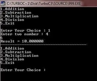
CÓMO HACER UNA CALCULADORA DE CUATRO FUNCIONES EN CPP: Las calculadoras se utilizan para todos en la vida diaria. Se puede hacer una calculadora simple usando un programa C ++ que es capaz de sumar, restar, multiplicar y dividir dos operandos ingresados por el usuario. La instrucción if y goto se usa para crear una calculadora
Arduino Nano - Tutorial de acelerómetro digital de 3 ejes de 12 bits / 8 bits MMA8452Q: 4 pasos
Arduino Nano - MMA8452Q Tutorial de acelerómetro digital de 3 ejes de 12 bits / 8 bits: El MMA8452Q es un acelerómetro inteligente, de baja potencia, tres ejes, capacitivo y micromaquinado con 12 bits de resolución. Se proporcionan opciones flexibles programables por el usuario con la ayuda de funciones integradas en el acelerómetro, configurables para dos interrupciones
Tutorial Python del acelerómetro digital Raspberry Pi MMA8452Q de 3 ejes de 12 bits / 8 bits: 4 pasos
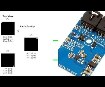
Raspberry Pi MMA8452Q 3-Axis 12-bit / 8-bit Acelerómetro digital Python Tutorial: El MMA8452Q es un acelerómetro inteligente, de baja potencia, tres ejes, capacitivo, micromecanizado con 12 bits de resolución. Se proporcionan opciones flexibles programables por el usuario con la ayuda de funciones integradas en el acelerómetro, configurables para dos interrupciones
DIY MusiLED, LED sincronizados con música con una aplicación de Windows y Linux con un clic (32 bits y 64 bits). Fácil de recrear, fácil de usar, fácil de portar: 3 pasos
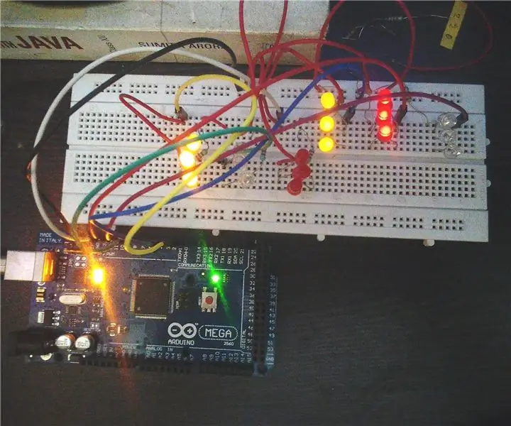
DIY MusiLED, LED sincronizados con música con una aplicación de Windows y Linux con un solo clic (32 bits y 64 bits). Fácil de recrear, fácil de usar, fácil de portar: este proyecto lo ayudará a conectar 18 LED (6 rojos + 6 azules + 6 amarillos) a su placa Arduino y analizar las señales en tiempo real de la tarjeta de sonido de su computadora y transmitirlas a los LED para iluminarlos según los efectos de ritmo (Snare, High Hat, Kick)
Cómo hacer un video de pantalla dividida con cuatro pasos: 4 pasos (con imágenes)

Cómo hacer un video de pantalla dividida con cuatro pasos: A menudo vemos a la misma persona en una escena dos veces en una obra de TV. Y hasta donde sabemos, el actor no tiene un hermano gemelo. También hemos visto que se colocan dos videos de canto en una pantalla para comparar sus habilidades de canto. Este es el poder de spl
